一. 产品介绍
1.1 产品概述
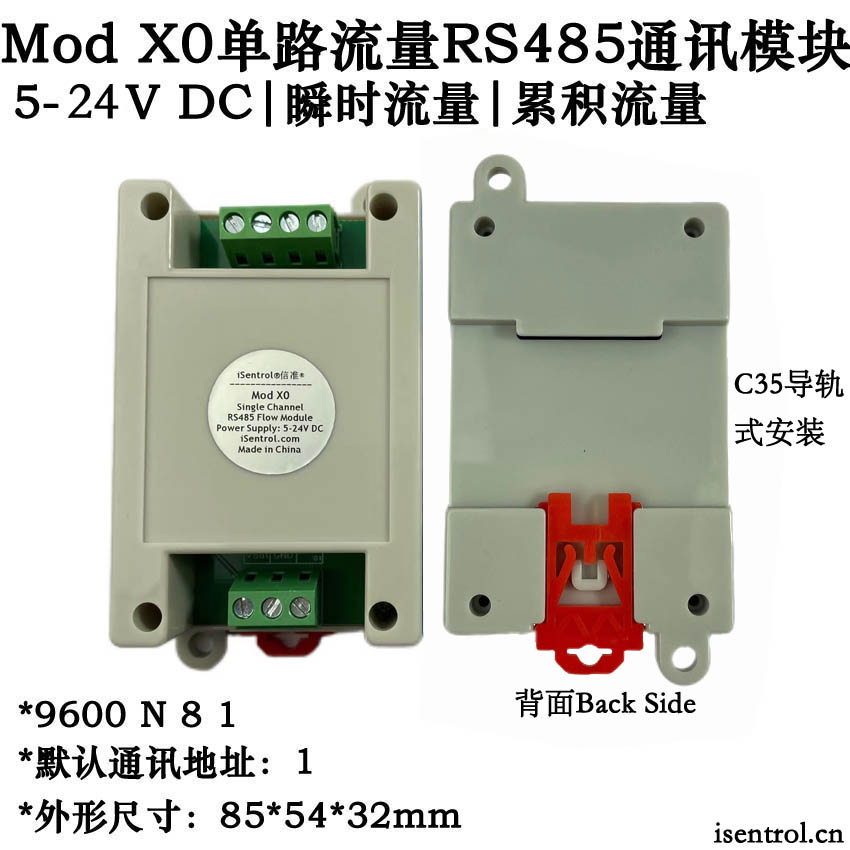
Mod X0拥有一通道,可给一路流量传感器连接,提供供电,采集脉冲信号,计算瞬时流量和总流量。可以通过标准的Modbus-RTU通讯协议对寄存器进行读写。可广泛应用于农业种植、自来水系统、工业自动化、物联网、无人机、智能家居等场所。
1.2 产品功能
* 支持标准的Modbus-RTU通讯协议
* 地址、波特率、恢复默认参数、查询参数、可设置,可修改,掉电保存;
* 内置看门狗,永不宕机、通电指示灯;
* DC5-24V宽压输入,防反接、过压保护、过流保护、短路保护:
* 防静电、雷击浪涌,抗干扰性强;
* 提供配套的PC端测试软件,方便调试、参数配置/修改。
1.3 产品特点
高速、高性价比、高精度、高可靠性、工业级;
工业级产品,满足不同领域的使用需求:
安装方便,标准C35(35mm)U型通用导轨安装。
1.4 产品参数
供电电压:5-24VDC
供电电流:<20mA@24VDC
通讯地址:1-255站号
波特率:4800/9600/19200/115200bps
通讯距离:0-1200米,通过中继器可以延长
参数复位:站号,波特率
工作温度:-20-60℃
安装方式:标准C35(35mm)U型通用导轨安装
外形尺寸:85*54*32(mm)
1.5 产品接线
上端Vin: 输入电源正
上端 GND:输入电源负
上端 B:接RS485的通讯接口负端B端
上端A:接RS485的通讯接口正端A端
下端Vout: 输出电源正(接水流传感器红线)
下端 GND:输出电源负 (接水流传感器黑线)
下端 FS 01: 流量信号输入(水流传感器的黄线)
下端 FS 02:无用
二. 通讯协议
2.1 指令表
产品采用标准的Modbus-RTU通讯协议,支持指令如下:
(1) 读保持寄存器功能码 0X03(十六进制) 03(十进制)
(2) 写单个保持寄存器功能码 0X06(十六进制) 06(十进制)
(3) 写多个保持寄存器功能码 0X10(十六进制) 16(十进制)
Modbus RTU寄存器列表如下:
| 功能码 | 中文名称 | 寄存器PLC地址 | 操作类型 | 操作数量 |
| 0X03/03 | 读保持寄存器 | 40001-49999 | 字操作 | 单个或多个 |
| 0X06/06 | 写单个保持寄存器 | 40001-49999 | 字操作 | 单个 |
| 0X10/16 | 写多个保持寄存器 | 40001-49999 | 字操作 | 多个 |
2.2 默认通讯参数
地址: 1;
波特率 : 9600bps;
数据位:8bit;
停止位:1bit;
奇偶校验:无;
2.3 保持寄存器(0X03功能码)定义
主机可通过标准Modbus RTU协议读写保持寄存器参数,寄存器中的数值为16位无符号整数。蓝色字体参数掉电保存,参数修改后需要重新上电有效。绿色字体参数掉电保存
| 协议地址 | PLC地址 | 默认值 | 寄存器功能描述 | 单位 | 最大值 |
| 0000H | 40001 | 2 | 波特率(0:2400; 1:4800; 2:9600; 3:19200; 4:115200) | 4 | |
| 0001H | 40002 | 1 | 设备地址,设置范围是1-255 | 255 | |
| 0002H | 40003 | 2 | 精确到几位小数 | 3 | |
| 0003H | 40004 | 500 | 水流传感器参考K值,读写的数值是实际值的100倍 | 65535 | |
| 0004H | 40005 | 永久累计流量高位 | L | 65535 | |
| 0005H | 40006 | 永久累计流量低位 | L | 65535 | |
| 0006H | 40007 | 永久累计流量小数位,读写的数值是实际值的100倍 | L | 99 | |
| 0007H | 40008 | 永久累计流量脉冲值(累积1L进位) | Hz | 65535 | |
| 000DH | 40014 | 临时累计流量高位 | L | 65535 | |
| 000EH | 40015 | 临时累计流量低位 | L | 65535 | |
| 000FH | 40016 | 临时累计流量小数位,读写的数值是实际值的100倍 | L | 99 | |
| 0010H | 40017 | 临时累计流量脉冲值(累积1L进位) | Hz | 65535 | |
| 0011H | 40018 | 瞬时流量,读数是实际值的 100 倍 | L/min | 65535 | |
| 0012H | 40019 | 实时脉冲数(仅供参考) | Hz | 65535 |
2.4 通讯数据示例
例1: 读单个保持寄存器:读取瞬时流量
指令:0x01 0x03 0x00 0x11 0x00 0x01 0xd4 0x0F ( 01 03 00 11 00 01 d4 0f )
站号:01
功能码:03
起始地址:00 11转为10进制为17
寄存器个数: 00 01表示一位寄存器
CRC校验:D4 0F 低位在前,高位在后
注意⚠️:读取到的数值缩小100倍才是实际的瞬时流量,单位是L/Min(升每分钟)。
例2:写单个保持寄存器:修改设备地址为2
指令:0x01 0x06 0x00 0x01 0x00 0x02 0x59 0xCB (01 06 00 01 00 02 59 cb )
站号:01
功能码:06
起始地址:00 01转为10进制为1
寄存器目标值:00 02转为10进制为2
CRC校验:59 CB 低位在前,高位在后
2.5 常用指令
(1) 功能:修改设备地址为3
指令:01 06 00 01 00 02 59 cb
(2) 功能:读取瞬时流量数值
指令:01 03 00 11 00 01 d4 0f
(3) 功能:永久累计总流量清零
指令:01 10 00 04 00 04 08 00 00 00 00 00 00 00 00 47 B5
(有关永久累积流量的寄存器需要同时清零,即寄存器4/5/6/7要同时清零。)
(4) 功能:读取永久累计总流量
指令:01 03 00 04 00 03 44 0A
(所有指令均可通过Modbus调试助手获取,详情请参阅:http://us211m.cn/news/shownews.php?lang=cn&id=41 )
2.6 硬件重置
重置按键位置:电路板上金属按钮,标有RESET标识
重置范围:站号和波特率,站号重置为1,波特率重置为9600
操作方法:按住RESET金属按键后上电,继续保持按压10秒钟
2.7 注意事项:
(1) 地址、波特率、K 值、永久累计流量各项数值修改后,需要重启设备才能生效。
(2) 累计流量清零前请关闭输入管道,防止清零后又有水流经过,60 秒后数值变动,程序再次更改数值导致累积量无法归零。
(3) 临时累计流量断电后清零,永久累计流量每 60 秒记录一次。(60 秒内必须超过 1 升的流量变动才会记录)
(4) 寄存器低位存满65535后会向高位进1。示例:假设一路流量传感器 累计流量高位读数为1,累积流量低位读数为2,那么总流量为65535*1+2=65537L
(5) 每一个寄存器的最大存储数值为65535,每一路流量传感器的永久累积流量最大存储数据为65535*65535+65535=42亿9千490万1760升水
(6) 清零操作时,有关永久累积流量的寄存器需要同时清零,即寄存器4/5/6/7要同时清零。临时累积流量清零也要按照此规则。
(7) 如果遗忘站号和波特率,可以通过硬件重置。按住RESET金属按键后上电,继续保持按压10秒钟可恢复站号和波特率的出厂值。
三. 上位机软件
软件名称:Mthings摩尔信使
Mod X0配置文件:Mod_X0.mthings
四. 视频介绍
五.技术支持
名称:山东信准电子科技有限公司
地址:山东省济南市历城区仲宫镇上海街21-1号5单元
联系人:张先生
手机:13001715332
微信号:13001715332
邮箱:info@isentrol.com
I.Product Introduction
1.1 Product Overview
Mod X0 has one channel that can be connected to a flow sensor.It provides power supply,collects pulse signals,and calculates
both instantaneous and total flow rates.The device supports read and write operations on registers via the standard Modbus-RTU
communication protocol.It can be widely applied in various fields
such as agricultural planting,water supply systems,industrial automation,the Internet of Things,drones,and smart homes.
1.2 Product Features
• Supports the standard Modbus-RTU communication protocol.
• Address,baud rate,reset to default parameters,query parameters,and settings can be modified and saved even after power loss.
• Built-in watchdog to prevent system crashes and a power-on indicator light.
• Wide input voltage range of DC 5-24V with protection against reverse connection,overvoltage,overcurrent,and short circuit.
• Protection against static electricity and lightning surges,with strong anti-interference capabilities.
• Comes with a PC-based testing software for convenient debugging,parameter configuration,and modification.
1.3 Product Highlights
• High-speed,high cost-effectiveness,high precision,high reliability,industrial-grade.
• Industrial-grade product that meets the usage requirements of different fields.
• Easy installation with standard C35(35mm)U-type universal rail mounting.
1.4 Product Specifications
• Power supply voltage:5-24VDC
• Power supply current:<20mA@24VDC
• Communication address:Station numbers from 1 to 255
• Baud rate:4800/9600/19200/115200 bps
• Communication distance:0-1200 meters,extendable via repeaters
• Parameter reset:Station number,baud rate
• Operating temperature:-20-60℃
• Installation method:Standard C35(35mm)U-type universal rail mounting
• Dimensions:855432(mm)
1.5 Wiring Diagram
• Upper Vin:Positive power input
• Upper GND:Negative power input
• Upper B:Negative end of the RS485 communication interface
• Upper A:Positive end of the RS485 communication interface
• Lower Vout:Positive power output(connect to the red wire of the flow sensor)
• Lower GND:Negative power output(connect to the black wire of the flow sensor)
• Lower FS 01:Flow signal input(connect to the yellow wire of the flow sensor)
• Lower FS 02:Not used
II.Communication Protocol
2.1 Instruction Table
The product uses the standard Modbus-RTU communication protocol and supports the following instructions:
• (1)Read Holding Registers Function Code:0X03(Hexadecimal)03(Decimal)
• (2)Write Single Holding Register Function Code:0X06(Hexadecimal)06(Decimal)
• (3)Write Multiple Holding Registers Function Code:0X10(Hexadecimal)16(Decimal)
The Modbus RTU register list is as follows:
Function Code Chinese Name Register PLC Address Operation Type Operation Quantity
0X03/03 Read Holding Registers 40001-49999 Word Operation Single or multiple
0X06/06 Write Single Holding Register 40001-49999 Word Operation Single
0X10/16 Write Multiple Holding Registers 40001-49999 Word Operation Multiple
2.2 Default Communication Parameters
• Address:1;
• Baud rate:9600bps;
• Data bits:8bit;
• Stop bits:1bit;
• Parity:None;
2.3 Holding Registers(Function Code 0X03)Definition
The host can read and write the parameters of the holding registers via the standard Modbus RTU protocol.
2.4 Communication Data Examples
Example 1:Read a Single Holding Register-Reading Instantaneous Flow
• Command:0x01 0x03 0x00 0x11 0x00 0x01 0xd4 0x0F(01 03 00 11 00 01 d4 0f)
• Station number:01
• Function code:03
• Starting address:00 11(decimal 17)
• Number of registers:00 01(one register)
• CRC check:D4 0F(low byte first,high byte second)
Note⚠️:The value read should be divided by 100 to get the actual instantaneous flow rate,in units of L/Min(liters per minute).
Example 2:Write a Single Holding Register-Changing Device Address to 2
• Command:0x01 0x06 0x00 0x01 0x00 0x02 0x59 0xCB(01 06 00 01 00 02 59 cb)
• Station number:01
• Function code:06
• Starting address:00 01(decimal 1)
• Target value of register:00 02(decimal 2)
• CRC check:59 CB(low byte first,high byte second)
2.5 Common Commands
• (1)Function:Change device address to 3
• Command:01 06 00 01 00 02 59 cb
(2)Function:Read instantaneous flow value
Command: 01 03 00 11 00 01 d4 0f
(3)Function:Reset permanent cumulative total flow to zero
Command: 01 10 00 04 00 04 08 00 00 00 00 00 00 00 00 47 B5
(Registers related to permanent cumulative flow need to be reset simultaneously,i.e.,registers 4/5/6/7 must be reset at the same time.)
(4)Function:Read permanent cumulative total flow
Command: 01 03 00 04 00 03 44 0A
(All commands can be obtained via the Modbus Debugging Assistant.
2.6 Hardware Reset
• Reset Button Location:Metal button on the circuit board,marked with the RESET label.
• Reset Range:Station number and baud rate.The station number is reset to 1,and the baud rate is reset to 9600.
• Operation Method:Power on while holding the RESET metal button,and continue pressing for 10 seconds.
2.7 Precautions
(1)After modifying the address,baud rate,K value,and permanent cumulative flow values,the device needs to be restarted
for the changes to take effect.
(2)Before resetting the cumulative flow to zero,close the input pipeline to prevent water from passing through after the reset.
If the value changes within 60 seconds and the program modifies the value again,the cumulative flow may not be able to reset to zero.
(3)The temporary cumulative flow is reset to zero after power loss,while the permanent cumulative flow is recorded every 60
seconds.(A flow change of more than 1 liter within 60 seconds is required for recording.)
(4)When the low byte of a register is full(65535),it increments the high byte by 1.For example,if the high byte of the cumulative flow
for a flow sensor reads 1 and the low byte reads 2,the total flow is 655351+2=65537L.
(5)The maximum storage value for each register is 65535.The maximum storage data for the permanent cumulative flow of each flow
sensor is 6553565535+65535=4,294,967,296 liters of water.
(6)During the reset operation,registers related to permanent cumulative flow must be reset simultaneously,i.e.,registers 4/5/6/7
must be reset at the same time.The temporary cumulative flow reset should also follow this rule.
(7)If the station number and baud rate are forgotten,they can be restored to their factory values through hardware reset.
Power on while holding the RESET metal button and continue pressing for 10 seconds to restore the station number and baud rate
to their factory settings.
III.Host Computer Software